
Startseite » Produkte » Andere Produkte » Optical Rotary Joints
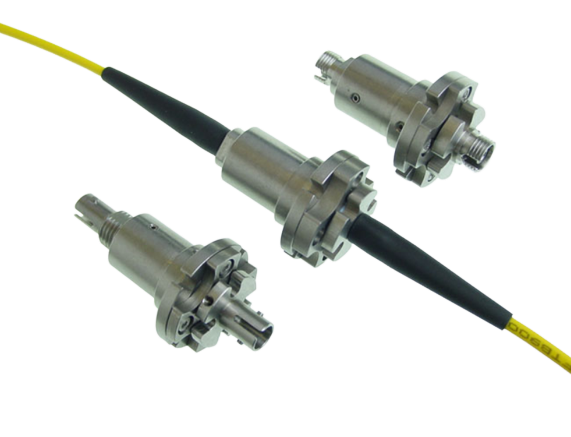
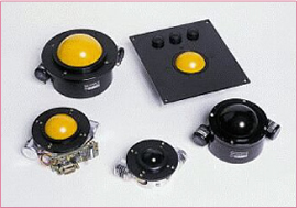
Joysticks are the most suitable hand controller for dynamic applications such as the remote operation of a vehicle or camera tracking system. They are available in two basic forms: ‘force sensitive’ or the more traditional ‘displacement’
type where the handle is free to move through an arc of typically ±20 degrees.
Joysticks are the most suitable hand controllers for dynamic applications such as remote vehicle operation and camera tracking systems, and displacement joysticks are the most common type. Our modular displacement joystick range has been developed specifically for applications that require robustness and reliability combined with optimum accuracy and a user-friendly feel.
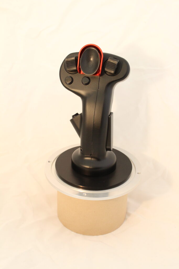
Our MP1 modular displacement joystick is designed for ultimate reliability and performance. It features:
A range of options are available so you can configure your device to meet your needs.
| Electrical | ||
|---|---|---|
| Excitation | Voltage | 5 ± 0.5 VDC |
| Current | 150 mA + output current | |
| Output voltage, per encoder | TTL compatible true square wave on output A (yellow) and B (orange). | |
| High | 2.7V min. | |
| Low | 0.8V max. | |
| Output current, per encoder | 18 mA max sink; Fan out of 10 TTL | |
| Insulation, per encoder | >10M ohms at 500V | |
| Direction sensing | + X | XB leads XA by 90 ± 30° |
| + Y | YA leads YB by 90 ± 30° | |
| Typical Resolution | 1.5 inch ball | 150 pulses per ball revolution |
| 2.0 inch ball | 200 pulses per ball revolution | |
| 2.5 inch ball | 250 pulses per ball revolution | |
| 3.0 inch ball | 300 pulses per ball revolution | |
| Mechanical | ||
|---|---|---|
| Storage temperature | MT4 series | -60°C to +90°C |
| MT6 series | -10°C to +55°C | |
| Operating temperature | MT4 series | -40°C to +70°C |
| MT6 series | 0°C to +50°C | |
| Humidity | MT4 series | Up to 100% non-condensing |
| MT6 series | Up to 95% non-condensing | |
| MTBF | Trackball only | 100,000 hours 2 million ball revolutions |
| Assumes a level of routine maintenance | ||
Laden Sie sich jetzt die Datenblätter herunter:
Force-operated joysticks use strain gauges attached to a fixed metal post to convert applied force into a proportional electrical output. Typically a movement of less than 1mm is needed to achieve full-scale output. Daco force-operated joysticks consist of a force-sensitive spring fixed into a base and surrounded by a housing.
The force applied to the spring in the plane parallel to the base is resolved into X and Y components. These are sensed separately by strain gauges bonded to the spring and connected to form two half Wheatstone bridges. The resulting analogue output has infinite resolution and is proportional to input voltage and applied force.
Force-operated joysticks are noteworthy for their small footprint. They require less space for mounting and the base assembly is smaller than an equivalent displacement joystick; if a grip is fitted no space is needed to accommodate an arc of travel.
Daco’s force-operated joysticks provide full proportional control yet take no more space than a simple switch. Our devices typically have a body length of approximately 25mm. This makes them ideal for fitting in control grips, such as MG1, for use as thumbsticks. The low mass of the thumbsticks reduces their sensitivity to vibration and increases the effectiveness of mechanical damping.
Despite their size, our force-operated joysticks are extremely resilient, having an overload capability factor of 10. We have tested all our products to 10,000,000 cycles, with each cycle being full scale in both +ve and -ve directions. All units are fitted with an internal protective bellows that can be supplemented with an external elastomer seal. These features, coupled with the use of fully anodised aluminium exposed components, mean that the devices are suitable for the most demanding applications.
MJ3 modular force-operated joysticks are two-axis devices that use strain gauges to convert applied force into an infinite resolution analogue output, proportional to input voltage and the force applied. They have the following characteristics:
The small size of our MJ3 joystick – typically 25mm – lends itself to a variety of mounting arrangements, including fitting in control grips such as Daco’s MG1.
Force Joysticks – Technische Daten
The Daco MP3 force-operated joystick is extremely robust, small and easy to use.
| Electrical | ||
|---|---|---|
| Excitation | Rated | 10V or ± 5VDC |
| Maximum | 12V or ± 6VDC | |
| Input resistance | 650 Ohms nominal | |
| Output | Resistance (per half bridge) | 325 Ohms nominal |
| No force | ±125mV maximum | |
| Sensitivity | 95mV/N nominal | |
| Full scale (FS) | 1.0 ± 0.2VDC | |
| Balance (+FS to -FS) | 200mV maximum | |
| Resolution | Stepless | |
| Non-linearity | ±1% FS maximum | |
| Hysteresis at zero | ±0.3% FS maximum | |
| ±1.0% FS maximum if elastomer seal used | ||
| Interaction | ±5% maximum | |
| Zero offset thermal drift | ±0.04% FS/°C typical | |
| Insulation | >50M Ohms at 50VDC | |
| Mechanical | ||
|---|---|---|
| Force, full scale | 10.5N nominal | |
| Force, maximum | ±0.35mm nominal | |
| Deflection, full scale | 10.5N nominal | |
| Weight | 25gms maximum | |
| Life | >3x10^6 FS cycles | |
| Temperature | Operating | -40 to +70°C |
| Storage | -55 to +90°C | |
| Sealing (panel sealed) | BS 5490 IP67 | |
| External materials (front of panel) | Anodised aluminium alloy | |
| Epichlorohydrin 60 (elastomer seal) | ||
| Joystick body | Black anodised | |
| Joystick knob | Black anodised | |
Laden Sie sich jetzt die Datenblätter herunter:
The modular trackballs are available in two versions – the MT4 and the MT6. The MT4 is higher specification and is therefore the more popular choice for more demanding environments. The MT6 is commonly used for less extreme applications.
The modular trackballs are available in two versions – the MT4 and the MT6. The MT4 is higher specification and is therefore the more popular choice for more demanding environments. The MT6 is commonly used for less extreme applications.
Trackballs – Technische Daten
| Electrical | ||
|---|---|---|
| Excitation | Voltage | 5 ± 0.5 VDC |
| Current | 150 mA + output current | |
| Output voltage, per encoder | TTL compatible true square wave on output A (yellow) and B (orange). | |
| High | 2.7V min. | |
| Low | 0.8V max. | |
| Output current, per encoder | 18 mA max sink; Fan out of 10 TTL | |
| Insulation, per encoder | >10M ohms at 500V | |
| Direction sensing | + X | XB leads XA by 90 ± 30° |
| + Y | YA leads YB by 90 ± 30° | |
| Typical Resolution | 1.5 inch ball | 150 pulses per ball revolution |
| 2.0 inch ball | 200 pulses per ball revolution | |
| 2.5 inch ball | 250 pulses per ball revolution | |
| 3.0 inch ball | 300 pulses per ball revolution | |
| Mechanical | ||
|---|---|---|
| Storage temperature | MT4 series | -60°C to +90°C |
| MT6 series | -10°C to +55°C | |
| Operating temperature | MT4 series | -40°C to +70°C |
| MT6 series | 0°C to +50°C | |
| Humidity | MT4 series | Up to 100% non-condensing |
| MT6 series | Up to 95% non-condensing | |
| MTBF | Trackball only | 100,000 hours 2 million ball revolutions |
| Assumes a level of routine maintenance | ||
Laden Sie sich jetzt die Datenblätter herunter:
Sie haben Fragen oder wünschen sich eine Beratung?
Teilen Sie uns Ihre technischen Anforderungen oder Fragen gern schriftlich über das verlinkte Kontaktformular mit. Nach Ihrer Anfrage werden wir uns umgehend bei Ihnen melden.